
All components must be taken into account when designing a facade with dry installation technology:
- thermal insulation
- type of stone material
- types of static loads
- selection of structural anchors for facade installation
Insulation of the structural wall
An important element of the stone facade is the insulation of the structural wall. The most commonly used insulation material is 100 x 60 cm stone wool slabs (e.g. Ventirock F Plus by Rockwool). The wool slabs are covered on one side with a black glass fibre veil. They are fixed to the structural walls, black veil on the outside, using facade dowels with a driven pin with plates.
Each mineral wool slab should be fixed to the substrate with the appropriate number of dowels in accordance with the manufacturer’s guidelines. To install the anchor in the wall, a hole with a diameter of approx. 15 cm must be cut in the mineral wool. Once the anchor has been installed, the cut-out section of mineral wool returns to its place, ensuring the continuity and tightness of the insulation.
Setting the anchors
Anchors are set into structural walls using quick-setting cement mortar. Their embedding depth is a minimum of 8 cm and depends on their overhang and the material of the wall. For reinforced concrete walls this depth generally does not exceed 10 cm, for brick walls 12 cm. The anchors are made of stainless steel, which guarantees the safety and durability of the stone cladding for decades.
It should be noted that thermal bridges created by the anchoring of facade slabs must be taken into account in the calculation of the U heat transfer coefficient for the wall.
Stone slabs and loads
The main element of the facade, however, is the stone slabs. They cause the static load for the entire wall and carry the dynamic loads caused by wind pressure and suction. The most important load is the weight of the stone slabs themselves. The table below shows the specific weights of the different stone types.
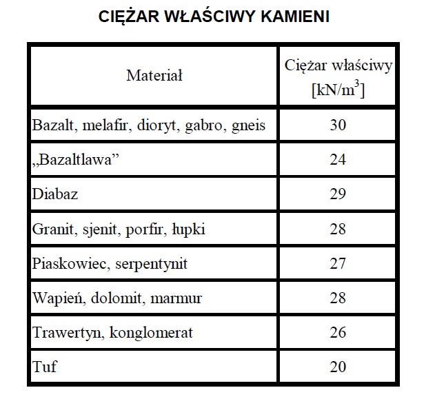
These characteristics, together with the distance of the facade slab from the structural wall (known as the overhang), form the basis for calculating and selecting suitable anchors. The connecting element between the anchor and the stone slab is a bolt which, through an ABS sleeve, forms a flexible joint.
Wind loads
A very significant load on the facade is the forces caused by wind pressure and suction. These forces add up. The wind load (W) is determined by the formula W = Cp x Q, where Q [kN/m2] is the wind pressure dependent on wind speed and height of the structure, and Cp is the aerodynamic pressure factor.
The aerodynamic factor depends on the angle of impact of the airflow, the exposure of the facade and its height. For ventilated facades it ranges from -3.2 to +1.0. German standards set the ratio of open joint area to facade area at a minimum of 0.75 per cent, which is provided by a joint 8 mm wide.
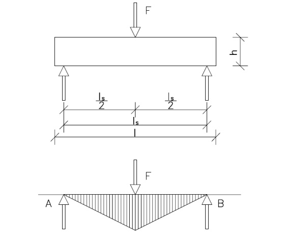
Different rocks have very different resistance to bending. Diabase is the most resilient, with a factor of 15 to 25 N/mm2. The weakest are tuffs and limestones with 2 to 8 N/mm2. Sandstones, dolomites and marbles have 6 to 15 N/mm2, while granites, gabbro, syenites, diorites and quartzites have 10 to 22 N/mm2.
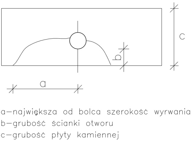
Wind load forces are also very important in determining the resistance of a stone slab to anchor bolt pull-out. These forces are transferred directly from the whole slab to four bolts embedded in its sides.
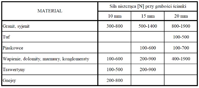
The following table shows as an example the destructive forces on the stone at different wall thicknesses of the opening (b) in the facade slab. These are only auxiliary values, as the actual value is determined case by case by testing samples of the specific stone material.
The calculation scheme
Appropriate computer programs are used to calculate stone facades. The calculation scheme is always the same. The support anchor located in the vertical joint carries half the load of the left and right slab. The support anchor located in the horizontal joint transfers the load from the edge of the slab to half the distance to the second support anchor.
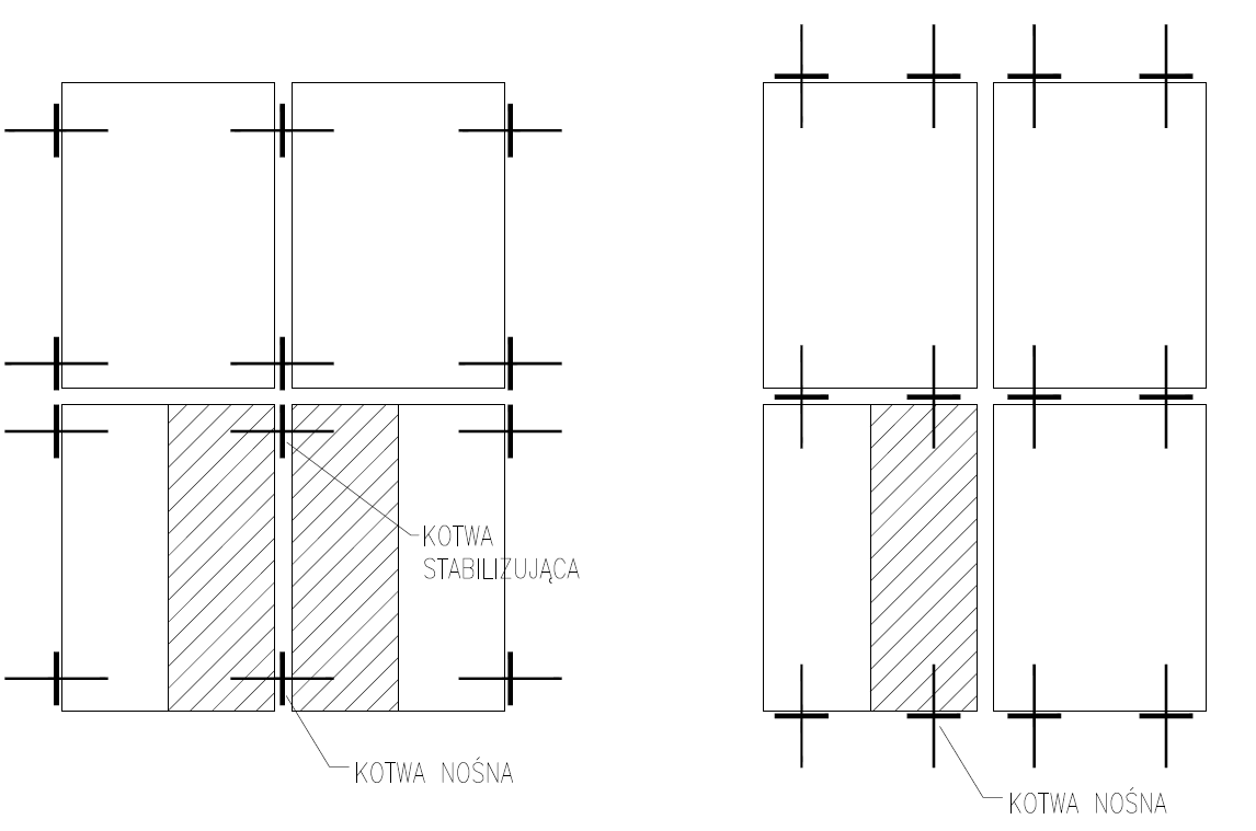
The second important element for the calculation is the anchor overhang, i.e. the distance of the axis of the anchor bolt from the face of the wall in which the anchor is embedded. With the above data, the anchors are selected from the Roko Systems product catalogue.